描述
- Hign-concerned Chemical: None
- is_customized: Yes
- Model Number: HW-373
- Type: Voltage Regulator
- Brand Name: NoEnName_Null
- Origin: Mainland China
- Condition: New
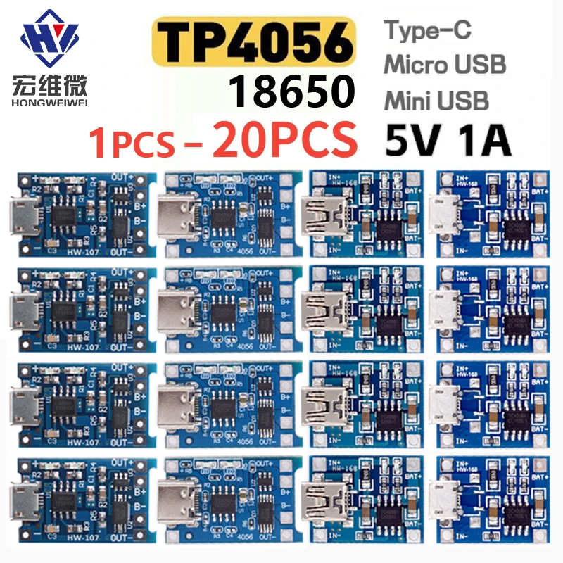
Micro Type-c USB 5V 1A TP4056 Lithium Battery Charger Module Charging Board With Protection Dual Functions Current Protection
Product features:
Charging protection, preventing overcharging and overdischarging of the battery, and automatically controlling the charging current to better protect the battery;
Type-C/Micro USB/Mini USB female socket interface, with reserved input voltage for soldering, convenient for DIY.
Product parameters:
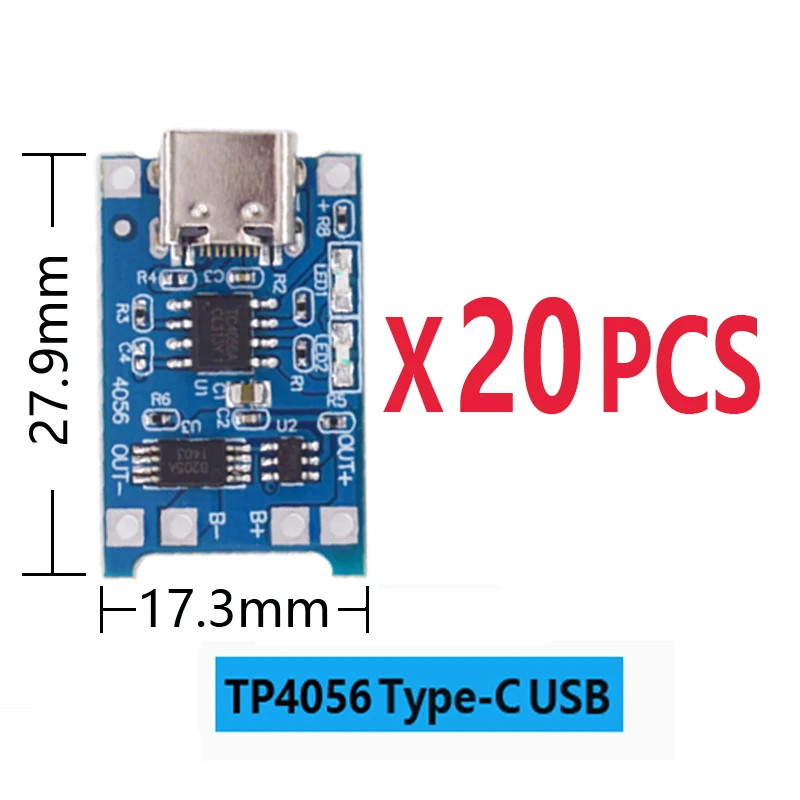
Input voltage: 4.5V-5V
Maximum charging current: 1000Ma
Charging cut-off voltage: 4.2V ± 1%
Battery over discharge protection voltage: 2.5V/3A
usage method:
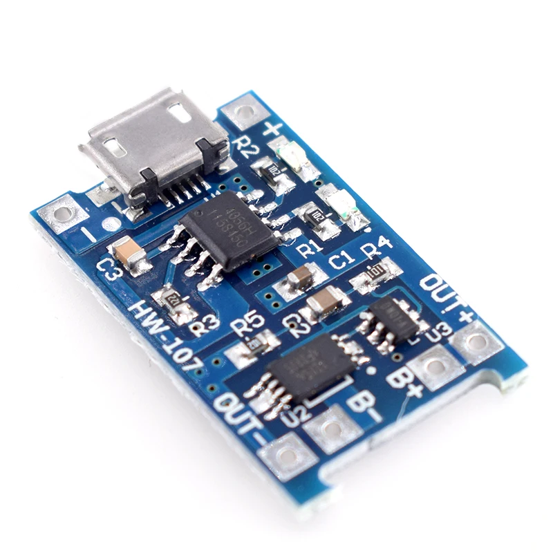
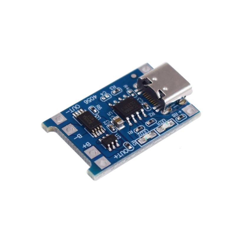
Type-C mother socket and its adjacent+- pad power input terminal, connected to 5V input voltage. B+is connected to the positive pole of the lithium battery, and B – is connected to the negative pole of the lithium battery. OUT+OUT – Connect to a load, such as a boost board. Connect the battery to B+B -, plug in the phone charger to USB, the blue light is on, indicating power is connected, and the red light is flashing, indicating charging. After being fully charged, the red light stops flashing and becomes constantly on.
You can connect the load at the OUT+OUT – end, and after connecting the load, the red light will remain on. When there is a power supply at the input end, current is obtained from the power output end. If there is no power supply, current is obtained from the battery. When the battery voltage is below 2.5V, the output is automatically turned off.
Product parameters
1. Input voltage: DC4.5V-5.5V; IN+IN pad wiring or MicroUSB 5V input;
2. Full charge voltage: DC4.2V;
3. Charging current: 1A adjustable;
4. Equipped with a charging indicator light;
5. Working temperature: -10 ℃~+85 ℃
Instructions for use
After power on, the blue indicator light of the module stays on, and the red indicator light flashes slightly;
When the battery is fully charged, the red and blue indicator lights of the module remain on;
be careful:
1. The wiring should distinguish between positive and negative poles, and reverse connect the burnt IC;
2. Charging requires short and thick wires to connect. If the wires are too thin or too long, the connection resistance will be high, and after charging, the battery voltage will drop more;
3. Connect the wires well, otherwise the battery voltage will drop more after charging is completed;
4. The output current can be adjusted by changing the fixed resistor in the circuit board to change the output current from 100mA to 1000mA;
If the 5V input voltage is too high, such as 5.2V or 5.5V, it will cause the charging current to be less than 1000mA, which is normal. When the voltage is high and the chip heats up, it will automatically reduce the charging current and lower the chance of the chip being burned;
6. If the charging current is too high or used in a high-temperature environment, heat dissipation treatment is required;
7. The ammeter for testing current can only be connected in series with the 5V input terminal of the charging board;
8. The satisfactory charging current should be 0.37 times the battery capacity. For example, a charging current of 400mA for a 1000mAh battery is sufficient;
9. If the charging speed is fast, the charging effect will be poor, and the more the battery voltage drops after charging is completed;
Product Introduction:
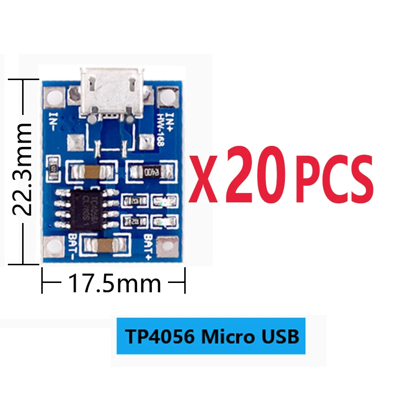
1. Input voltage: DC 5V;
2. Charging cut-off voltage: 4.2V ± 1%;
3. Maximum charging current: 1000mA;
4. Battery over discharge protection voltage: 2.5V;
5. Battery overcurrent protection current: 3A;
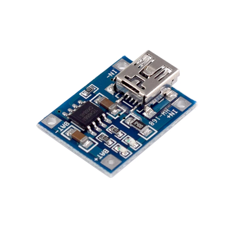
6. The input terminal is equipped with a MICRO USB socket, which can be directly used as an input power source to charge the lithium battery with a mobile phone charger;
usage method:
1. The MICRO USB socket and its adjacent+- pads are the power input terminals, with B+connected to the positive pole of the lithium battery and B – connected to the negative pole of the lithium battery. OUT+and OUT – can be connected to loads, such as the positive and negative poles of a mobile boost board or other loads.
2. Connect the battery to B+B -, insert the phone charging cable into the USB socket, the red light is on to indicate charging, and the blue light is on to indicate full charge.
Application: It can be used for charging and discharging protection of 18650, polymer, and other lithium batteries with voltages of 3.6V and 3.7V. It can also be used in parallel with single or multiple batteries.
be careful:
When connecting the battery for the first time, there may be no voltage output between OUT+and OUT -. In this case, charging the module with DC 5V voltage can activate the protection circuit. If the battery is disconnected from B+B – and reconnected, it also needs to be charged to activate the protection circuit. When using a mobile phone charger as an input power source, it is important to note that the charger and charging cable must be able to support a current output of 1A, otherwise it may cause the module to not charge the battery properly;
When charging the battery, the load on the OUT terminal should be disconnected, and the positive and negative poles should not be connected incorrectly. Please use according to the specifications, otherwise the module will be damaged.

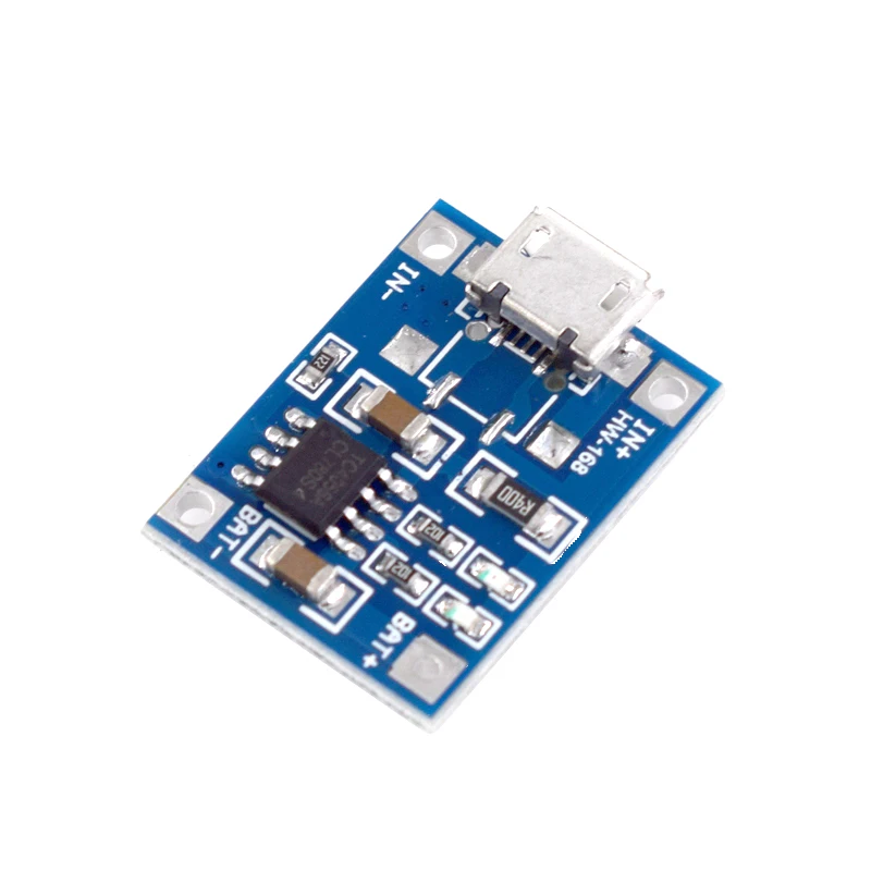
Product parameters
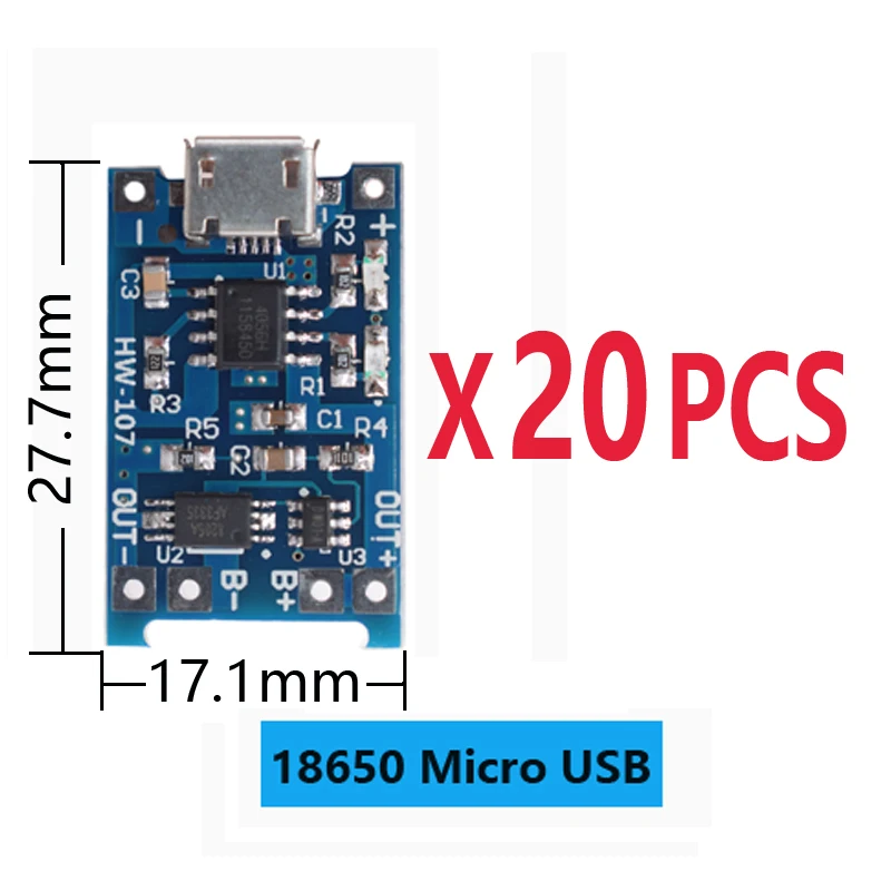
1. Input voltage: DC4.5V-5.5V; IN+IN pad wiring or MiniUSB 5V input;
2. Full charge voltage: DC4.2V;
3. Charging current: 1A adjustable;
4. Equipped with a charging indicator light;
5. Working temperature: -10 ℃~+85 ℃;
usage method:
After power on, the blue indicator light of the module stays on, and the red indicator light flashes slightly;
When the battery is fully charged, the red and blue indicator lights of the module remain on;
1. The wiring should distinguish between positive and negative poles, and reverse connect the burnt IC;
2. Charging requires short and thick wires to connect. If the wires are too thin or too long, the connection resistance will be high, and after charging, the battery voltage will drop more;
3. Connect the wires well, otherwise the battery voltage will drop more after charging is completed;
4. The output current can be adjusted by changing the fixed resistor in the circuit board to change the output current from 100mA to 1000mA;
If the 5V input voltage is too high, such as 5.2V or 5.5V, it will cause the charging current to be less than 1000mA, which is normal. When the voltage is high and the chip heats up, it will automatically reduce the charging current and lower the chance of the chip being burned;
6. If the charging current is too high or used in a high-temperature environment, heat dissipation treatment is required;
7. The ammeter for testing current can only be connected in series with the 5V input terminal of the charging board;
8. The satisfactory charging current should be 0.37 times the battery capacity. For example, a charging current of 400mA for a 1000mAh battery is sufficient;
9. If the charging speed is fast, the charging effect will be poor, and the more the battery voltage drops after charging is completed;


评价
目前还没有评价